
A plastic injection molding machine is a critical asset in modern manufacturing, enabling high-precision plastic parts to be made in short cycle times. To maximize effectiveness, manufacturers should understand the construction and the role of each assembly. In this article, Thai Duong Plastics analyzes the main components of an injection molding machine and the technical parameters to watch.
Detailed overview of a plastic injection molding machine’s construction
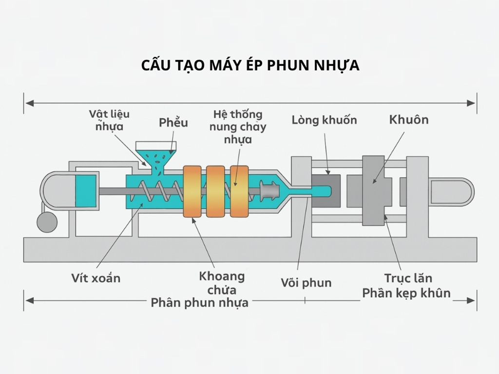
A standard injection molding machine is divided into three primary systems: the injection unit, the clamping unit, and the control unit. In addition, auxiliary systems help keep the process stable. Working in concert, these systems form a closed cycle: material feeding, heating, injection, packing/holding, cooling, and part ejection.
Injection Unit
This is the heart of the machine, converting solid pellets into a homogeneous melt and injecting it into the mold with controlled speed and pressure.
Heated barrel and screw
The heated barrel is a thick steel tube divided into multiple temperature zones to control melting. Inside is a helical screw with three sections: feed, compression, and metering. The screw both rotates to homogenize the melt and reciprocates to inject it into the mold.
Key parameters-such as compression ratio, back pressure, and the screw’s L/D (length-to-diameter) ratio-directly affect melt quality.
Nozzle and non-return valve
The nozzle connects the screw/barrel to the mold. A check ring (non-return valve) on the screw acts like a one-way valve, preventing backflow during the packing/holding phase.
Material feeding and drying
The hopper feeds pellets into the barrel. Hygroscopic resins like PET, PA (nylon), and PC require drying/dehumidifying equipment. Inadequate drying leads to bubbles, splay, or reduced part properties.
Clamping Unit
The clamping unit keeps the two mold halves closed during injection and holding, then opens the mold and ejects the part.
Platens and guidance
The clamp comprises a stationary platen and a moving platen that travels on tie bars (guide rods) to open/close the mold. Platen stiffness and parallelism govern wall-thickness uniformity and dimensional consistency.
Clamping force generation
Two main mechanisms are used: a toggle linkage, which develops very high force at the end of stroke (ideal for parts needing high clamp force), and direct drive via hydraulic cylinders or electric actuators (ball screws). Clamp force must be sufficient to resist cavity pressure; too little causes mold opening and flash.
Ejection and mold protection
After solidification, ejector pins/plates remove the part. Mold-protection functions use sensors to halt motion upon detecting obstructions, preventing mold and machine damage.
Control Unit
This is the machine’s command center, allowing operators to set, monitor, and adjust every parameter of the cycle.
Cycle control
A digital controller sets repeatable parameters: individual zone temperatures, multi-stage injection speeds and pressures, holding time/pressure, cooling time, mold-open sequence, ejection timing, and more. Control precision determines cycle-to-cycle repeatability.
Sensors and closed-loop control
Modern machines use temperature and pressure sensors for closed-loop operation. Controlling to actual pressure (including in-mold pressure where applicable) stabilizes shot weight and minimizes dimensional variation.
Data logging and diagnostics
The control system records process data, tracks cycle metrics, and alerts on anomalies, enabling predictive maintenance and reducing unplanned downtime.
Auxiliary systems
Injection machines are typically integrated with several auxiliaries to stabilize production:
- Cooling: Water/oil circuits remove heat from the mold and barrel. Flow and temperature directly affect surface gloss and cycle time.
- Pneumatics and vacuum: Used for slides/cores, venting, or ejection assistance.
- Automatic lubrication: Reduces wear on tie bars and toggle mechanisms.
- Safety devices: Guards, interlocks, and emergency-stop circuits ensure safe operation.
Applying machine construction to selection and use
Machine construction directly informs machine selection and part quality. Consider the notes below to choose the right configuration and limit defects during production.
Selecting machine configuration by product type
Each product group has distinct technical needs, so the machine configuration should match:
- Thin-wall, large-area parts require a high-output injection unit, a longer L/D screw, and higher clamping force to prevent mold opening.
- Optical parts benefit from a low-compression screw to minimize shear heating, plus highly parallel platens for accurate clamping.
- Insert molding is suited to vertical presses with rotary tables, easing core loading and enhancing mold protection.
- Glass-/fiber-filled materials call for wear-resistant screws and heavy-duty guidance components.

See also: What is an injection mold? Structure, classifications, and applications
Common defects linked to machine design/setting
Some defects stem directly from system settings or machine construction:
- Flash along the parting line often comes from insufficient clamp force or platen deflection.
- Short shots or burn marks can result from a cold nozzle or leakage at the check ring.
- Voids/bubbles arise when back pressure is too low or venting is inadequate.
- Inconsistent shot weight is frequently tied to a leaking non-return valve or variable screw friction.
Commissioning procedure after installing a new mold
A typical procedure includes: checking platen parallelism; setting barrel/mold temperatures per resin recommendations; configuring staged injection speeds for optimal filling; defining an appropriate transfer point to holding; setting holding pressure for stable dimensions; optimizing cooling time; and saving the validated process recipe. Proper commissioning extends mold life and stabilizes part quality.
The construction of an injection molding machine-its injection, clamping, and control units plus auxiliaries-directly affects quality, cost, equipment longevity, and competitiveness. Understanding and operating in line with that construction stabilizes quality, optimizes costs, and enhances your edge. For further advice, contact Thai Duong Plastics for prompt support.
Reference: Common types of industrial injection molding machines